Are you struggling to get the right fit for your custom excavator parts? I know how frustrating it is when a new batch of rollers or pins arrives but won’t fit.
Defining tolerances for non-standard undercarriage parts requires balancing ISO 286 fit classes, like H7/g6 for sliding parts, with the specific demands of heavy-duty construction environments to ensure long-term durability and proper field performance.
It is easy to get lost in technical charts and numbers. If you want your machines to run smoothly without breaking down, you need to understand how we set these limits. Let’s dive into the details of tolerances and fits.
Should I use ISO fits (H7/g6) for my pins and bushings?
When you order custom pins, you might wonder if a standard H7/g6 fit is the right choice for your heavy equipment. I often see customers worried that these standards are too strict for a dirty construction site.
Using ISO fits like H7/g6 for pins and bushings is highly recommended as it provides a "close running fit" that allows for necessary lubrication while preventing excessive play and vibrations.
Understanding the H7/g6 Fit in Undercarriage Parts
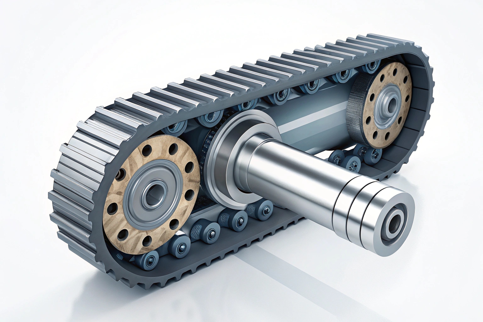
In my 20 years of manufacturing experience at Dingtai, I have found that the ISO 286 system 1 fit is the "gold standard" for parts that need to move. The H7 represents the hole (the bushing), and g6 represents the shaft (the pin). This combination ensures there is always a tiny gap, or clearance, between the two parts.
In the world of excavators, this gap is not just "extra space." It is where the grease lives. Without this specific clearance, the metal surfaces would rub directly against each other. This leads to heat build-up and, eventually, the pin seizing inside the bushing. For a machine working in a mine or a busy construction site, a seized pin means a complete stop in work.
When to Choose Different Fit Classes
Not every part of the undercarriage moves. Some parts must stay frozen in place. This is where we change our approach. We use different "classes" of fits based on what the part does.
| Fit Category | ISO Example | Typical Application | Movement Type |
|---|---|---|---|
| Clearance Fit | H7/g6 | Track Roller Shafts | Free Rotation |
| Transition Fit | H7/js6 | Idler Brackets | Precision Positioning |
| Interference Fit | H7/p6 | Bushing into Track Link | Permanent Press-fit |
The Impact of Precision on Wear Life
If you choose a fit that is too loose, the parts will "clatter." This impact loading damages the hardened surface of the pins. On the other hand, if it is too tight, the parts will gall. We use the GB/T 1800.2-2020 2 standard, which aligns with ISO, to make sure every part we ship from our Fujian factory meets these exact needs. For critical parts like track pins, we aim for IT6 to IT8 precision levels. This level of detail is what separates a part that lasts 5,000 hours from one that fails after 1,000.
What surface roughness do my sliding fits need?
Many people focus only on the diameter of a part, but I have seen perfectly sized parts fail because the surface was too rough. It is like trying to slide two pieces of sandpaper against each other.
Sliding fits in excavator undercarriages require a surface roughness (Ra) of 0.4 to 0.8 micrometers to maintain a stable oil film and prevent rapid initial wear during the break-in period.
Why Surface Finish Matters More Than You Think
When we talk about tolerances, we must talk about surface finish. If a shaft is machined to the right size but has a rough surface, the "peaks" of that roughness will wear down almost immediately. This is called "running-in" wear. Once those peaks are gone, your carefully calculated dimensional tolerance 3 is gone too. The fit becomes loose, and the part starts to fail.
Recommended Roughness Values
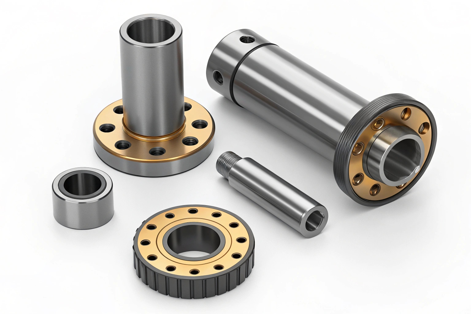
For our B2B clients, we provide specific data on surface finishes. We use grinding processes after heat treatment to achieve these smooth finishes.
- Track Roller Shafts: Ra 0.4 μm. This is very smooth and allows the seals to work perfectly without leaking oil.
- Standard Pins: Ra 0.8 μm. This provides a good balance between cost and performance.
- Non-moving Structural Parts: Ra 3.2 μm to 6.3 μm. These don’t need to be smooth, so we save the customer money by not over-polishing them.
Comparing Finish and Performance
| Part Name | Recommended Ra (μm) | Machining Method | Risk of High Roughness |
|---|---|---|---|
| Track Bushing (Outer) | 0.8 | Fine Turning/Grinding | Accelerated link bore wear |
| Track Pin (Surface) | 0.4 – 0.6 | Precision Grinding | Seal failure and oil leaks |
| Sprocket Teeth | 3.2 | Milling | Increased chain vibration |
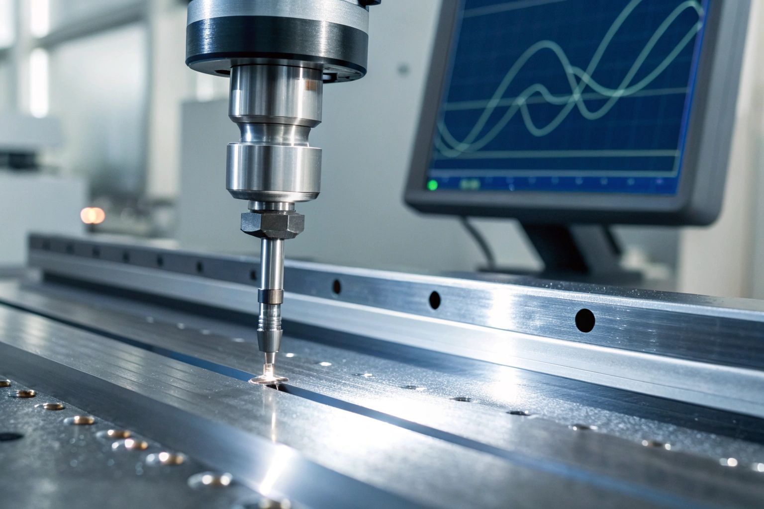
At Dingtai, we use 100% quality inspection. We don’t just look at the part; we use profilometers 4 to measure these tiny microscopic valleys. For a procurement manager like David, this consistency is the difference between a happy end-user and a costly warranty claim.
Can I set concentricity and runout limits?
I once had a client who complained that their rollers were wearing unevenly. After checking their technical drawings, I realized they hadn’t specified concentricity. The hole wasn’t perfectly in the middle of the roller.
Setting concentricity and runout limits, typically within 0.05mm to 0.1mm, is essential for non-standard rollers and idlers to ensure even load distribution and prevent premature bearing failure.
The Danger of "Off-Center" Parts
Concentricity means that the center of the inner hole and the center of the outer circle are the same. If a track roller is even slightly "off-center," it will hop as it rotates. Imagine driving a car with oval-shaped wheels. You would feel every bump, and your tires would wear out in days. In an excavator, this "hop" creates massive shock loads on the bearings and the track chain 5.
How We Define These Limits
For non-standard or custom parts, you should always include these GD&T symbols 6 on your drawings:
- Total Runout: This measures how much the surface moves in and out as the part spins. For a standard roller, we keep this under 0.1mm.
- Concentricity: This ensures the bearing seats on both sides of a roller shell are perfectly aligned. If they are not aligned, the shaft will be tilted, putting all the pressure on one side of the bearing.
Technical Checklist for Custom Orders
When you send us a request for a custom undercarriage part, your technical team should specify:
- Primary Datum: Usually the central axis of the shaft or the bore.
- Tolerance Zone: The allowable "wobble" (e.g., 0.08mm).
- Measurement Method: We use Coordinate Measuring Machines 7 to verify these for our high-end OEM clients.
How do I specify heat-treatment alongside tolerances?
One mistake I see often is specifying a tight tolerance but forgetting that heat treatment changes the size of the metal. If you machine a part to a perfect H7 fit and then heat-treat it, it will warp.
Specify heat-treatment requirements, such as induction hardening depth (3mm-10mm) and surface hardness (HRC 45-60), before final grinding to ensure that the finished part meets both strength and tolerance specifications.
The Relationship Between Heat and Size
Steel expands and contracts when it is heated to 800°C and then quenched in water or oil. This process is necessary to make the parts "tough" enough for rocks and mud. However, it also causes distortion. If you want a pin to be exactly 50.00mm, we must machine it slightly larger, heat-treat it, and then perform a "final grind" to reach the target size.
Key Heat-Treatment Specs for Undercarriage Parts
| Component | Material | Hardness Requirement | Hardening Depth |
|---|---|---|---|
| Track Link | 35MnB | HRC 52 – 58 | 5mm – 8mm |
| Track Pin | 40Cr / 42CrMo | HRC 55 – 60 | 3mm – 5mm |
| Track Bushing | 20CrMnTi | HRC 58 – 62 | 2mm – 4mm |
Providing a Complete Specification
When you talk to a manufacturer like us at Dingtai, don’t just say "make it hard." Give us the specific Rockwell Hardness 8 range and the "effective case depth." The case depth is how deep the hardness goes. If it is too shallow, the "hard shell" will crush like an eggshell. If it is too deep, the part becomes brittle and will snap under impact.
We provide material reports and induction hardening 9 data for every batch. This transparency helps buyers like David Miller trust that the "non-standard" part will perform just as well, if not better, than the original OEM specifications 10.
Conclusion
Defining tolerances is about finding the balance between precision and practical performance. By using ISO fits, controlling roughness, and planning for heat treatment, you ensure your custom parts fit perfectly and last longer.
Footnotes
1. Official ISO 286 guide for limits and fits in engineering. ↩︎
2. Chinese national standard for general tolerances and linear dimensions. ↩︎
3. Understanding the fundamentals of dimensional tolerances in manufacturing. ↩︎
4. Introduction to tools used for measuring surface roughness accurately. ↩︎
5. Expert discussion on track chain wear and alignment issues. ↩︎
6. Complete chart of Geometric Dimensioning and Tolerancing symbols. ↩︎
7. Learn how CMM machines ensure high-precision measurement for parts. ↩︎
8. Detailed explanation of the Rockwell hardness testing method. ↩︎
9. Overview of induction hardening for enhancing metal durability. ↩︎
10. Why adhering to OEM quality standards is vital for heavy machinery. ↩︎