
I know the frustration of ordering parts that almost fit. Without technical drawings 1, you are guessing, and guessing risks costly downtime for your entire fleet.
Yes, capable undercarriage suppliers can provide 3D models and technical drawings for engineering review. Manufacturers with in-house R&D teams typically offer STEP files and detailed PDF drawings to verify fitment, dimensions, and material specifications before mass production begins.
Let’s look at exactly what you should ask for to ensure you get the precision your machinery demands.
Which CAD formats (STEP/DWG) can I request?
You cannot check fitment if you cannot open the file. Incompatible software formats waste your engineering team’s time and delay critical approvals.
Standard requests include STEP or IGS files for 3D modeling and DWG or PDF files for 2D dimensional checks. These universal formats allow your engineering team to verify compatibility across different software platforms like SolidWorks, AutoCAD, or Inventor.

When we talk about engineering review, the file format is the key that unlocks the door. If I send you a file your team cannot open, it is useless. In the manufacturing world, especially for heavy machinery like bulldozers and excavators, we rely on universal formats.
The Difference Between 3D and 2D
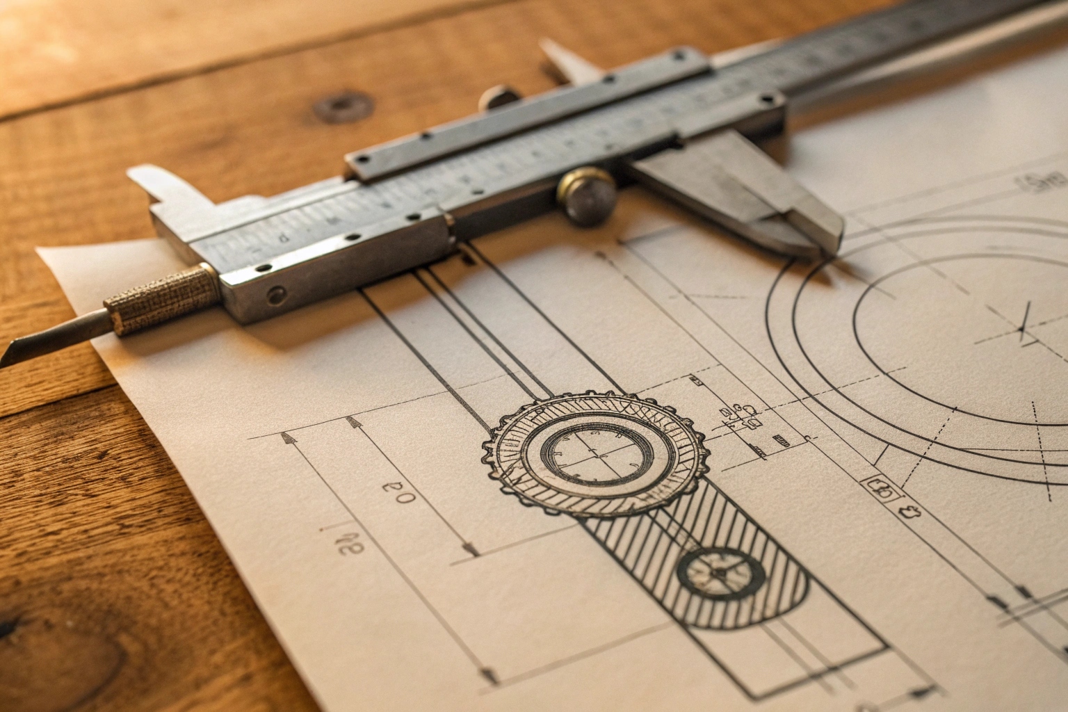
You should ask for both. A 3D model (like a STEP file) is excellent for "virtual assembly." Your engineers can drop our track roller into your digital excavator assembly to see if it clears the frame. It is the best way to catch big interference problems 2 early. However, 3D models rarely show tolerances. That is why you also need 2D drawings (DWG or PDF). The 2D drawing tells you the allowable variance in size, the heat treatment depth, and the surface finish.
I remember a client from Italy who only asked for the 3D model. The model was perfect. But when we produced the part, the pin fit was too tight because the specific tolerance wasn’t defined in the 3D file. Now, I always insist on sending both.
Common Formats and Their Purpose
Here is a simple breakdown of what you should ask for and why:
| File Format | Type | Primary Use Case |
|---|---|---|
| STEP (.stp) | 3D | Universal 3D format. Good for checking overall shape and fit in any CAD software like SolidWorks 3. |
| IGES (.igs) | 3D | Older 3D format. Useful for surface geometry if STEP fails. |
| DWG (.dwg) | 2D | Editable 2D drawing. Allows your engineers to add notes or their own title blocks in AutoCAD 4. |
| PDF (.pdf) | 2D | Locked document. Best for viewing dimensions, tolerances, and material specs without risk of accidental editing. |
For a supplier like us, providing these files is part of the service. It proves we actually manufacture the product and have the technical data to back it up. If a supplier refuses to give you at least a PDF drawing, be careful. They might be trading companies who do not want you to see the real source, or they simply do not control the quality.
A part usually fits on paper but fails in the field. Ignoring geometric tolerances leads to premature wear and catastrophic structural failures under heavy loads.
High-quality suppliers will share tolerance stacks and Geometric Dimensioning and Tolerancing (GD&T) data upon request. This critical information proves the manufacturer understands fit, form, and function, ensuring the parts interact correctly with your existing assembly.
This is where we separate the "part sellers" from the "engineering partners." Anyone can copy a dimension like "500mm length." But in undercarriage parts, the straight line isn’t the only thing that matters. The relationship between features is what keeps the machine running.
Why Simple Dimensions Are Not Enough
Imagine a track roller 5. It has a shaft and a body. If the hole for the shaft is the right size but is tilted slightly to the left, the roller will wobble. This wobble destroys the bushings and the seal, leading to oil leaks within weeks. Simple dimensions do not catch this tilt. That is where GD&T comes in.
When you review our drawings, you should look for specific symbols. These symbols tell you how much a feature is allowed to vary in shape or orientation. For example, "Concentricity" 6 ensures the center of the rim shares the exact same axis as the center of the hub. "Parallelism" ensures the mounting surfaces are perfectly flat relative to each other so the bolt heads sit flush.
Critical GD&T for Undercarriage Parts
If you are validating a new supplier, ask them to explain their GD&T standards for these specific areas:
| Symbol / Term | What It Controls | Why It Matters for Undercarriage |
|---|---|---|
| Concentricity | Center alignment | Prevents vibration in rollers and idlers. |
| Perpendicularity | 90-degree angles | Ensures sprockets align perfectly with the track chain. |
| Runout | Circular motion | Stops the part from "wobbling" as it rotates. |
| Flatness | Surface smoothness | Critical for track shoes to sit flat on the ground and link properly. |
We use these controls to manage the "tolerance stack" 7. This is the accumulation of small variations. If five parts connect, and each one is slightly off in the same direction, the final assembly will not fit. By controlling GD&T, we ensure that even with thousands of mass-produced parts, the final assembly always works. Never be afraid to ask for this data. A confident manufacturer will be proud to show you their precision.
Can I get exploded views for assembly manuals?
Your technicians struggle when assembly guides are unclear. Poor documentation slows down repairs and increases the risk of installation errors on the job site.
Suppliers with design capabilities can generate exploded views specifically for your service manuals. These visual aids simplify the installation process for end-users and help maintenance teams identify correct replacement part numbers quickly and accurately.
As a distributor or a large fleet manager, your job does not end when the parts arrive at the warehouse. You have to support the people installing them. This is where an exploded view becomes a powerful tool.
Visuals Bridge the Gap
I have worked with many procurement directors who are experts in negotiation but struggle with the technical complaints from their service teams. Often, the mechanic in the field has a pile of washers, seals, and bolts, and they aren’t sure which order they go in.
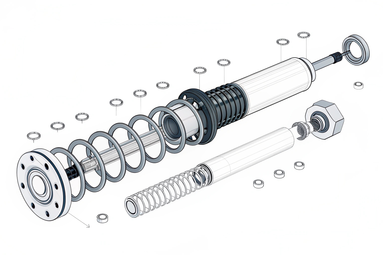
If we provide you with an exploded view drawing, we are essentially giving you a map. This drawing pulls the assembly apart to show every single component floating in its relative position. It shows exactly where the O-ring sits, which direction the seal lip faces, and the sequence of the locking washers.
Supporting Your Aftermarket Business
For my clients who resell parts under their own brand, these drawings are marketing gold. We can provide clean, unbranded line art that you can put into your own catalogs or service manuals 8. This makes you look more professional to your customers. It reduces the number of phone calls you get asking, "Does this spacer go on the left or the right?"
Here is how we typically structure these visual aids for our clients:
- BOM ID: Each part in the drawing has a number bubble.
- Part List: A table connects that number to your specific SKU.
- Kit Identification: We circle groups of parts that are sold as a repair kit (like a seal kit).
This level of support turns a simple transaction into a partnership. We are not just selling you steel; we are helping you sell a solution to your customers. If your current supplier cannot generate these views, it means they might not have the original design files, which is a red flag for quality control.
How do we control revisions across versions?
Receiving an outdated part version is a supply chain 9 nightmare. Without strict revision control, you risk stocking obsolete components that no longer fit your machines.
Revision control is managed through version numbers on drawings and change logs in the contract. A reliable supplier marks every drawing with a revision date and requires written approval before implementing any design changes to the production line.
In the world of engineering, nothing is static. Designs improve, materials change, and manufacturing processes evolve. However, these changes must be disciplined. If I change the diameter of a pin hole by 1mm and do not tell you, and you have 500 shafts in stock that fit the old hole, I have just cost you a fortune.
The Engineering Change Order (ECO)
We handle this through a formal process called the Engineering Change Order 10 (ECO). Before any change happens on the factory floor, it happens on paper (or digital paper).
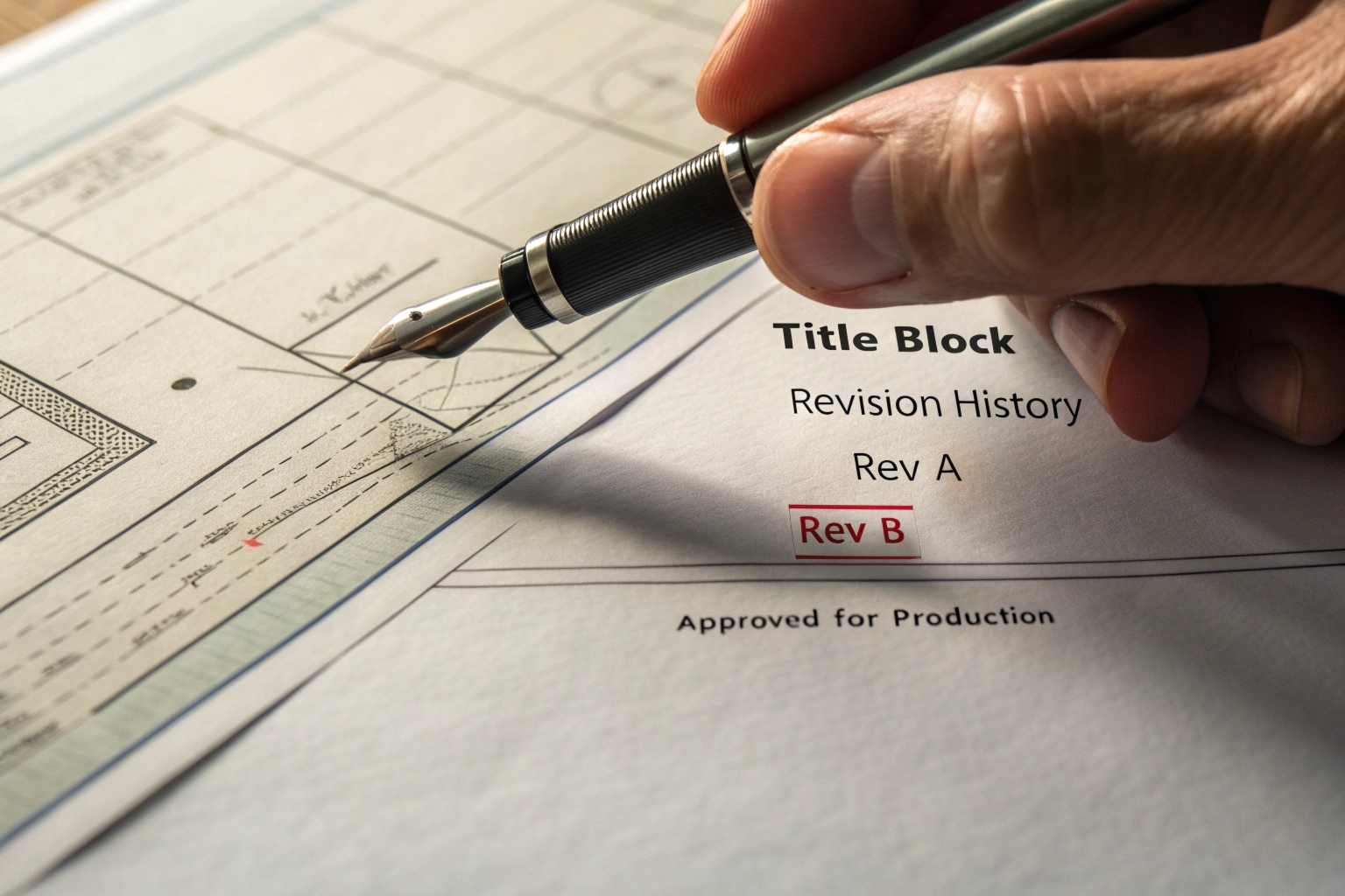
When we update a drawing, we update the revision block. This is a small box usually in the corner of the technical drawing. It will say "Rev A," "Rev B," etc. It records who made the change, when they made it, and briefly describes what changed.
Your Protection in the Contract
You need to enforce this in your purchasing agreement. You should require that:
- Notification: The supplier must notify you in writing of any form, fit, or function change.
- Approval: You must sign off on the new drawing before production starts.
- Traceability: The parts themselves should have batch codes that link back to a specific drawing revision.
Revision Control Checklist
Here is a quick checklist to use when setting up this process with a new supplier:
| Item to Check | Description |
|---|---|
| Title Block | Does the drawing have a clear revision letter/number (e.g., Rev 01)? |
| Change Log | Is there a history list on the drawing showing previous changes? |
| File Naming | Do digital files include the revision? (e.g., Roller_Asm_v2.step) |
| Approval Signature | Is there a space for your engineer to sign and date the approval? |
I once took over an account where the previous supplier had changed the heat treatment spec without updating the revision number. The parts looked the same but wore out in half the time. It took months to figure out why. Since then, I am obsessive about revision control. It protects both me as the manufacturer and you as the buyer. It ensures that the product you tested and approved is exactly the product you receive, shipment after shipment.
Conclusion
Technical transparency is the foundation of a reliable supply chain. By demanding 3D models, GD&T data, and strict revision control, you protect your business from costly errors and ensure consistent quality.
Footnotes
1. Definition of technical drawings for engineering verification. ↩︎
2. Overview of engineering interference fits in assemblies. ↩︎
3. Standard 3D CAD software for mechanical design. ↩︎
4. Leading software for 2D drafting and documentation. ↩︎
5. Explanation of continuous track components and mechanics. ↩︎
6. Guide to Concentricity in geometric dimensioning. ↩︎
7. Understanding cumulative tolerance variations in assemblies. ↩︎
8. Importance of user guides and service documentation. ↩︎
9. Definition and management of global supply chains. ↩︎
10. Process for managing engineering design changes. ↩︎