Nothing is worse than ordering a container of parts only to find bolt holes don’t align. I’ve seen too many downtime disasters caused by dimensional drift. We must fix this before shipping.
To verify compatibility, you must execute a three-step protocol: verify dimensions against OEM drawings, conduct a static test fit in the workshop, and perform field load testing. This sequence ensures rollers and chains align perfectly, preventing expensive rework.
It sounds tedious, but it is the only way to secure your supply chain. Many buyers just check part numbers, but that is not enough. Since chassis details vary by machine year and region, I will share how we use phased testing to manage quality risks and ensure every part fits like an original.
Should I run trial installations before bulk orders?
Skipping trial fits to rush a big order is gambling with your reputation. As a manufacturer, I strongly advise verifying dimensions on a small scale first to avoid huge losses.
You must run trial installations before bulk orders. It serves as the final defense against design deviations. By physically checking clearances, hole alignments, and interference in a static workshop setting, you control risks before shipment.
Why Static Fitting is Non-Negotiable
Many people think correct drawings mean correct products. But in manufacturing, tolerance control is a variable. We use a "three-level verification" method in our factory, and you should understand this process to demand the right standards from your supplier.
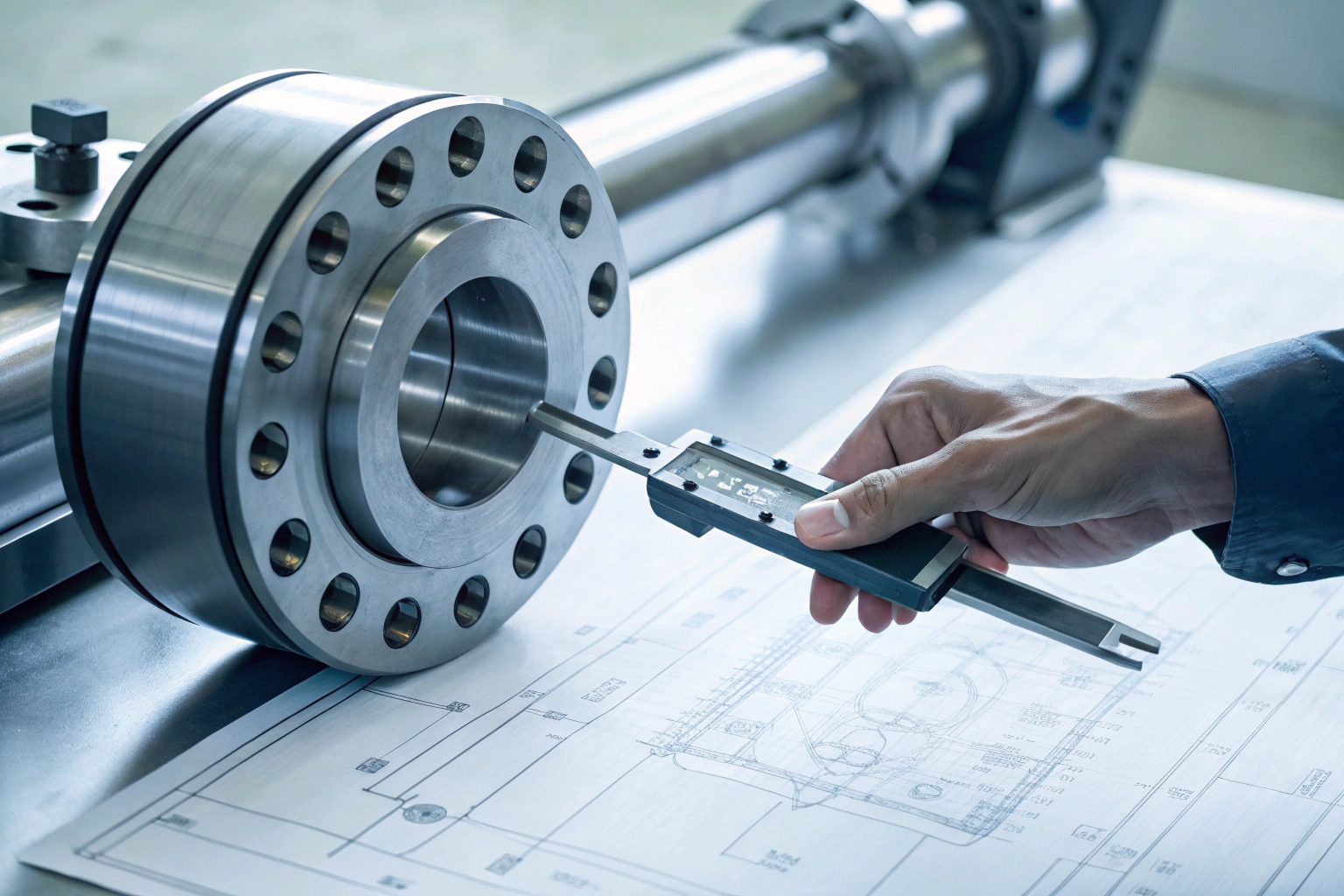
First, we check paper data compatibility. This is more than matching part numbers. We must compare key dimensions against the OEM manual and technical drawings 1. For example, the outer diameter of a track roller 2 defines the machine height, while track pitch affects ride smoothness. Even a 1mm deviation in bolt holes can cause installation failure. We also ensure material hardness and load ratings meet the host machine’s design standards.
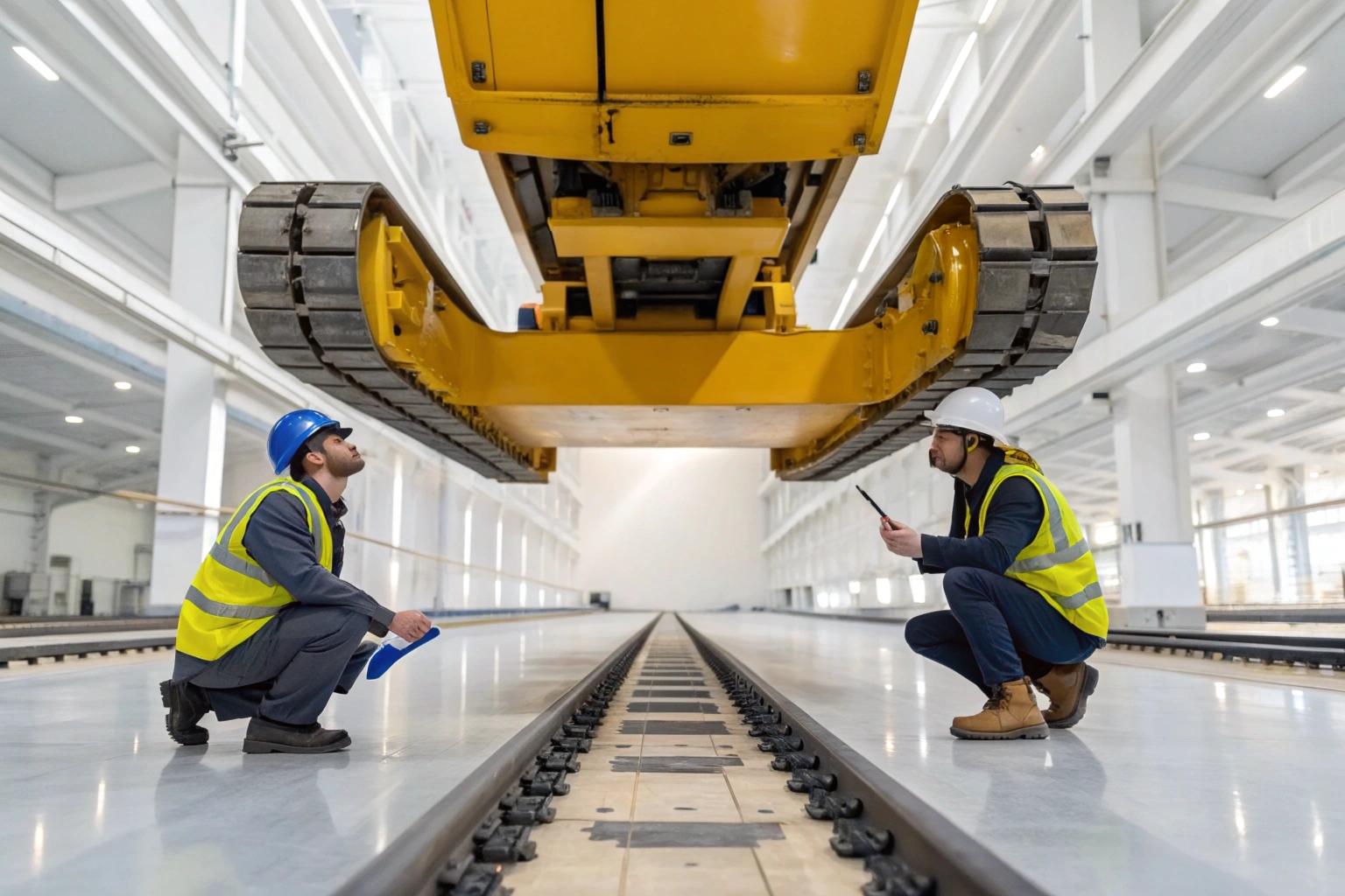
Next is the workshop static test fit. This is the most visual check. We install the parts on the specific chassis model. It is not just about bolting it on. We check assembly gaps. Is there enough side clearance between the track and idler? Are rollers and carrier rollers aligned? After tightening bolts to torque specs 3, does the part shift? Is there binding or strange noise?
Finally, we do a basic functional test. Without starting the engine or just at idle, we manually turn the drive sprocket 4. We watch for smooth track movement. If teeth skip or jam, the pitch or tooth profile is wrong. We also simulate lifting and turning to ensure no interference with hydraulic lines or guards.
Here is the standard table we use internally for judgment:
| Inspection Item | Key Focus | Pass Standard |
|---|---|---|
| Dimensions | Bolt spacing, Wheel OD, Shaft diameter | Deviation within drawing tolerance (usually ±0.5mm) |
| Installation Gap | Side play, Wheel spacing | No hard interference, even gaps, matches OEM manual |
| Fastening State | Mating surface, Torque | No gaps at mating surfaces, no loosening after torque |
| Operation Test | Manual turning, Low speed idle | Smooth running, no cyclic noise, no binding |
Only when all indicators show "no interference, correct gaps, no binding" do we pass the batch. If we find even a small issue, we stop and re-check the molds. Finding problems here costs the least; finding them after shipping costs a hundred times more.
Can I get sample sets for multiple machine models?
If your clients run mixed fleets, testing one model isn’t enough. You need to cover key sellers to fully assess a supplier’s capability and consistency.
Yes, you should request sample sets for multiple machine models. Reliable suppliers support mixed-sample testing because it validates their process stability across different operating conditions and chassis types before mass production begins.

Field Testing Strategies for Reliability
Success in the workshop is only half the battle. The real test is in the mud and mines. We call this "site-level reliability verification." This requires cooperation from you or your end-users to perform "destructive testing 5" in the field.
You can ask for samples for different models (e.g., CAT D6 dozer, Komatsu PC200 excavator). Real factories usually cooperate because we need this data too. Once you have samples, testing must follow a sequence.
Phase 1: No-Load Testing
Do not start with heavy work. Run the machine with new parts under no load. Drive on flat ground, turn, and climb small slopes (under 15°). Run this for at least 20 hours. We monitor the machine like a doctor. Watch heat buildup. If roller seals are bad, friction heat rises fast. Check wear patterns on new tracks. Check if bolts loosen from vibration.
Phase 2: Load Testing
After passing no-load, we get serious. Simulate real work. Load the bucket fully, lift heavy objects, or drive on mud and rock. Run this for at least 50 hours. Focus on Track Pitch Extension. If the chain stretches too fast, pin and bushing heat treatment 6 is too soft. Also, watch sprocket engagement for any skipping.
Phase 3: Extreme Testing (Optional)
For mining clients, this is vital. Find a steep slope (≥25°) for extreme turning and braking. This verifies impact resistance under high stress.
Recording data is key. Many clients just say "it’s okay" or "it failed," which helps no one. We need professional tools (like infrared thermometers 7) to record data.
Here is a structure for recording test data:
| Test Phase | Duration | Monitored Metrics | Target (vs OEM) |
|---|---|---|---|
| No-Load | 0-20 Hours | Wheel temp, Torque decay | Temp rise <40℃, Decay <5% |
| Load | 20-70 Hours | Pitch extension, Tooth wear | Deviation within ±5% |
| Extreme | 70+ Hours | Cracks, Seal leaks | Zero structural damage, Zero leaks |
With this structured testing, you get a detailed "health report," not a vague guess. This proves quality and serves as powerful evidence when selling to your end customers.
How do I collect field feedback to finalize specs?
Lab data is perfect, but field sites are chaotic. Only real feedback from operators tells us if the product is truly durable enough for daily abuse.
Collecting field feedback requires establishing a standardized tracking mechanism. By signing trial agreements with pilot customers and periodically collecting wear data and failure reports, you create a complete product profile to finalize specifications.

Building a Closed-Loop Feedback System
Many distributors cut contact after selling, waiting for complaints. This is passive quality management. To build a long-term edge, you need active "long-term combat verification."
Start with a Small Batch Pilot. Do not sell to everyone at once. Pick 3 to 5 trusted clients with different work conditions (e.g., one mining, one farming, one construction). Sign a trial deal, maybe offering discounts in exchange for data. Track them for 3 to 6 months.
Next is Regular Data Collection. Do not expect clients to write reports. Send sales staff weekly or monthly with a checklist, or ask for photos.
We need specific answers:
- Hours: How long did it run?
- Failures: Did tracks de-rail? Any leaks?
- Maintenance: Is track tension adjustment frequent?
- Physical Check: Measure roller wear diameter monthly to compare with OEM wear curves.
Closing the Loop is the core. If a client says "tracks de-rail often," it could be many things. Maybe dimension drift, soft material, or bad installation. We ask for photos and videos. If it is a dimension issue (like low idler rims), we fix drawings. If it is material, we adjust heat treatment.
We need a standard for success. We say: If no batch failures occur in the pilot, client satisfaction is over 90%, and projected life hits 80% of OEM parts, the product is compatible and qualified.
Here is a decision matrix to help manage feedback:
| Feedback Type | Symptom | Potential Cause | Our Action |
|---|---|---|---|
| Installation | Bolts won’t align | Hole coord tolerance bad | Fix CNC program, re-position drills |
| Performance | Fast early wear | Soft heat treat or wrong steel | Adjust quench process, deepen hard layer |
| Structural | Wheel crack/break | Casting flaw or weak design | Optimize mold, add ribs or change alloy |
| Fitment | De-railing/Noise | Gap too big or small | Adjust Idler/Link match dimensions |
By collecting and analyzing this feedback, we turn guesses into science. This solves current issues and sets a solid technical standard for your future bulk orders.
Will the supplier adjust tooling based on trials?
Finding issues during trials is fine; a supplier refusing to change is fatal. A true manufacturing partner is willing to adjust molds for you.
Yes, as a source factory, we adjust tooling based on trial feedback. This is part of OEM service, where we optimize dimensions or materials based on data to ensure the final product meets your market needs.

Customization and Tooling Adjustments
This question separates "traders" from "real manufacturers." Traders sell what they have. If it fits, good; if not, they give up. For factories like us, fixing molds is normal R&D work.
When trials show issues, we start an Engineering Change Notice (ECN) 8. This is a systematic process, not a quick patch.
For Dimensional Interference: If a roller mount rubs the frame, we check the 3D model to find the interference. We then modify the CNC program 9. For cast parts, we modify the pattern. Cutting steel is easy; changing casting molds costs money and time, but is necessary for quality.
For Material Performance: If wear resistance is low, we do not change molds. We change the "recipe." We adjust steel alloy (adding Boron or Manganese) or heat treatment (quench temp, temper time). This is process adjustment, a key part of custom service.
For Design Flaws: If a part breaks often, we use Finite Element Analysis (FEA) 10 to find stress points. We might add ribs to the mold or add chamfers to spread stress.
You need to know that adjusting molds takes time and money.
- Minor Fixes: Larger holes, chamfers. Takes 1-2 weeks. Low cost.
- Major Changes: Shape change, flow gate change. Takes 3-4 weeks. Involves mold fees.
Usually, if our design misses OEM standards, we pay. If you want special changes for non-standard machines, we negotiate the cost.
We aim for "Joint R&D." When you ask for changes, we see it as a product upgrade, not a hassle. Your feedback represents real market needs. Through this tuning, we make a product that is not just a spare part, but a custom solution for your market. This is how we keep long-term partners globally.
Conclusion
Ensuring compatibility is science, not luck. From drawing checks to field tests, every step eliminates uncertainty. We stand ready to adjust our craft to build your most reliable product.
Footnotes
1. Overview of creating detailed engineering diagrams for manufacturing. ↩︎
2. Explanation of roller function within continuous track systems. ↩︎
3. Standards for tightening fasteners to ensure structural integrity. ↩︎
4. Definition of sprockets used to drive continuous tracks. ↩︎
5. Method of testing materials until failure to determine limits. ↩︎
6. Process of heating and cooling metals to alter properties. ↩︎
7. Guide on using non-contact thermometers for equipment monitoring. ↩︎
8. Documentation process for recording changes to engineering designs. ↩︎
9. How computer numerical control automates machine tool operation. ↩︎
10. Simulation method for predicting how parts behave under stress. ↩︎