Undercarriage parts must be flawless to ensure integrity. I find that defects such as porosity or cracks compromise their performance and are unacceptable.
Defect assessment standards for casting and forging undercarriage parts for excavators & bulldozer are stringent, adhering to ASTM and ISO benchmarks. Surface imperfections, internal cracks, and porosity beyond set limits often lead to rejection in the inspection process. These standards ensure the parts conform and perform efficiently without risk.
Understanding the intricacies of defect evaluations in undercarriage parts for excavators & bulldozer is complex. Let’s delve deeper into key criteria to maintain part quality and reliability.
What ASTM or ISO standard do you use for visual inspection of castings?
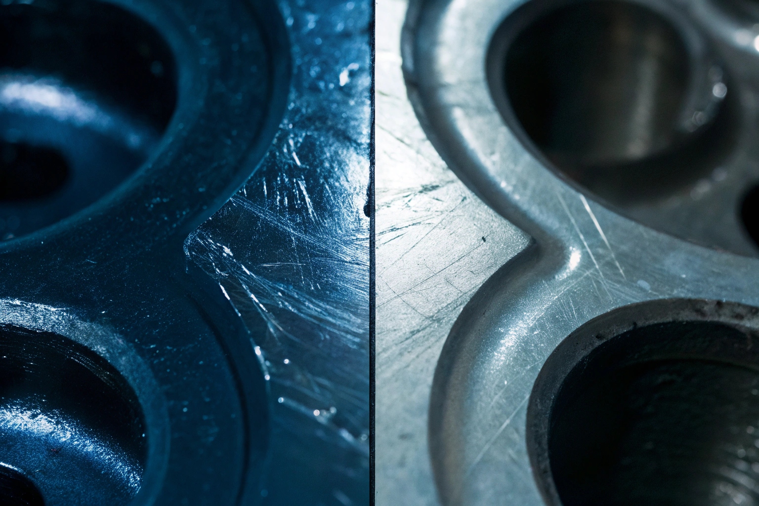
Visual inspection is key to ensuring casting quality. I focus on eliminating visible surface defects to preserve part integrity and durability.
Visual inspection standards for castings, like ASTM A609 and ISO guidelines, provide crucial benchmarks for assessing surface irregularities, porosity levels, and sand inclusions. These standards help identify defects, ensuring components meet operational demands.

Visual inspections are vital for identifying critical surface issues. Let’s explore how these standards are applied.
Visual Inspection Techniques and Standards
Visual inspection is the first step in defect identification. Through visual examination 1, I identify surface defects like cracks, pits, and sand inclusions. I use established standards, such as ASTM’s various criteria and MSS SP-55 2, to guide this process. Dimensional deviations 3 are checked against the tolerance levels to prevent misfits, ensuring seamless component integration upon usage.
Surface Evaluation Best Practices
The surface quality of these parts heavily influences their performance under stress. I apply industry rules, focusing on high-stress zones, adopting harsher standards for colder environments 4 where fracture risks are high. Visual inspections thus form a crucial element of integrity assurance.
What level of porosity or inclusions is considered acceptable?
Porosity must be minimal to ensure part longevity. High porosity spells trouble under operational stresses, reducing the part’s viability.
Acceptable porosity levels are defined by engineering standards. Generally, porosity below 2% of the total volume is ideal. Standards such as ASTM E446 and ISO guidelines dictate specific porosity and inclusion limits, crucial for parts crafted for heavy machinery.
Undercarriage parts must withstand operational rigor. Let’s delve into porosity acceptance criteria ensuring component resilience.
Porosity Impact on Structural Integrity
Excessive porosity leads to weak points, making components susceptible to stress and possible fractures. Acceptable porosity levels are vital in preventing structural failures in high-stress environments. I follow strict benchmarks, using established reference radiographs 5 to gauge severity and compliance with standards like ASTM E446 6. Importance is placed on maintaining porosity within allowable limits while assuring component strength and reliability.
Inclusion Size Limitations
Inclusion limits are set based on application requirements. For critical parts, inclusions must not exceed 0.3mm in diameter. Larger inclusions compromise the part’s structural integrity, leading to potential operational risks. For heavy-duty applications demanding high strength, zero porosity tolerance 7 is often the norm, ensuring parts hold up even under the most strenuous conditions.
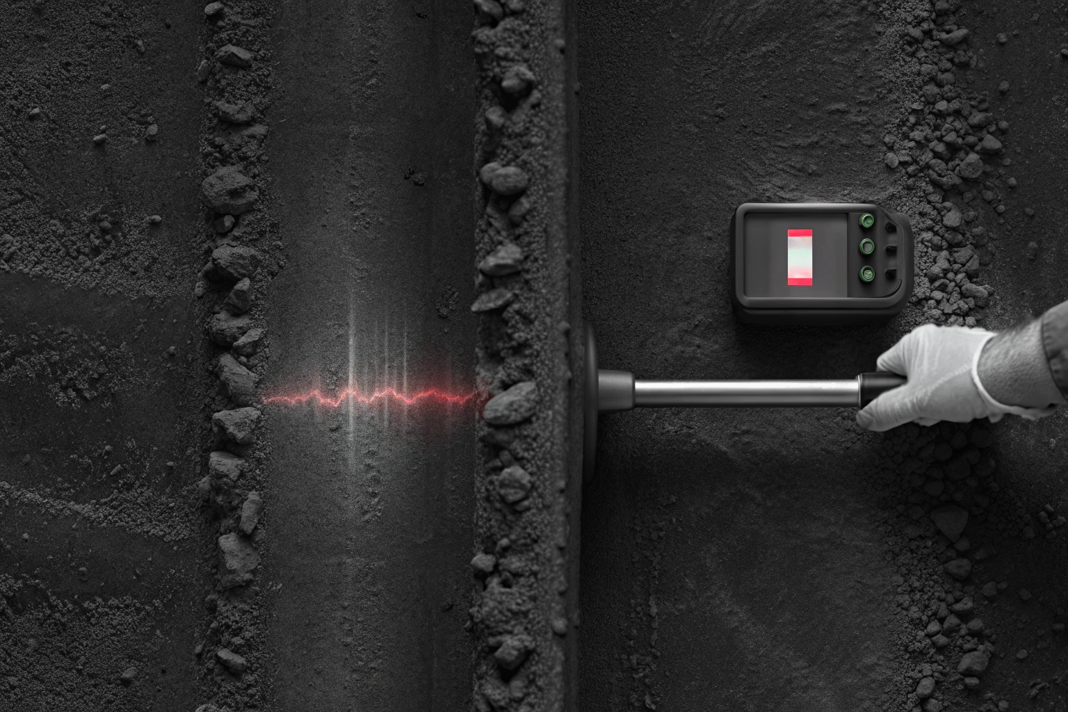
How do you test for sub-surface cracks in forged components?
Sub-surface cracks are dangerous. I employ precise testing techniques to detect and address them, ensuring parts achieve peak performance.
Testing for sub-surface cracks involves advanced methods like Ultrasonic Testing (UT) and Magnetic Particle Inspection (MPI). Standards like ASTM E446 and ISO provide guidelines ensuring comprehensive crack detection in forged components. These assessments are vital in preventing failure before application.
Detecting invisible cracks ensures component robustness. Let’s explore the testing standards preserving forged component excellence.
Non-Destructive Testing Methods
The pursuit of precision in testing underlines the importance of Non-Destructive Testing (NDT) techniques 8. I utilize Ultrasonic Testing (UT) to unveil hidden internal defects that might weaken the product during use. Magnetic Particle or Liquid Penetrant Tests (MPI or LPT) 9 are employed for surface-breaking cracks. Established ASTM guidelines dictate the procedures and benchmarks essential for confirming compliance with safety and performance standards.
Ensuring Forged Component Reliability
Forged components must be flawless, with uniform grain flow 10 and no discernible interruptions to prevent weaknesses. Sub-surface interruptions indicate potential weak points, needing stringent evaluations and adjustments. Crack evaluations are conducted in high-stress zones using ASTM benchmarks to confirm operational suitability and assure user safety.
Can I get the magnetic particle (MT) or ultrasonic (UT) test reports for my order?
Receiving test reports verifies component compliance. With MT and UT assessments, transparency in quality and safety is assured.
Test reports for Magnetic Particle (MT) or Ultrasonic (UT) assessments are available to ensure undercarriage components meet defect criteria. Documented evaluations offer transparency and assurance of component performance, upholding established ASTM and ISO benchmarks.

Reports are crucial for validating component integrity. Explore how testing documentation supports reliability and trust.
Documentation Practices
Test reports serve as tangible proof of compliance and integrity. I provide detailed documentation covering every inspection phase, ensuring transparency and accountability. Reports include technical specifics and evaluations confirming alignment with established standards like ASTM and ISO, reinforcing customer trust and satisfaction in the product’s quality and performance.
Ensuring Component Compliance
Component compliance is not a mere requirement but an assurance of lifespan and reliability. Each test report records the component’s conformity to stringent quality standards. Inspection data highlights identified challenges, facilitating resolution and ensuring components withstand operational stress. Compiling reports substantiates claims of compliance, guaranteeing customer assurance and component excellence.
Conclusion
Understanding and applying stringent defect standards preserves part integrity and promises operational reliability. Acceptable limits guide quality assurance, solidifying component performance under stress.
Footnotes
1. A guide to visual inspection techniques for metal castings. ↩︎
2. Details on the MSS SP-55 standard for visual inspection of castings. ↩︎
3. Understanding tolerance levels for casting dimensional accuracy. ↩︎
4. Learn how low temperatures impact material fracture risks. ↩︎
5. See examples of reference radiographs used to gauge defect severity. ↩︎
6. Read the official standard for steel casting reference radiographs. ↩︎
7. Why some heavy-duty applications demand zero porosity. ↩︎
8. An overview of common NDT methods in manufacturing. ↩︎
9. Comparing MPI and LPT for detecting surface-breaking cracks. ↩︎
10. The importance of grain flow in forged component strength. ↩︎